According to the information that can be found on the website of Sinopec, the Shengli Oilfield Petroleum Engineering Technology Research Institute has been tasked with the responsibility of carrying out fruitful research, designing, and developing integral metal screw pump technology. This information was obtained from the website of Sinopec. As a direct result of recent events, the Ministry of Science and Technology of Sinopec has granted not only an evaluation certificate but also an acceptance certificate for this forward-thinking piece of technology. The award was given as a result of recent occurrences. Since the same organization is responsible for issuing both of these certificates, this means that both of them carry the same level of credibility. It is a piece of machinery that has been constructed entirely out of metal, and at the same time, it serves as an example of the most recent and cutting-edge technological development in the field of the oil industry all over the world. An attempt has been made, through the development of this technological advancement, to address both of these concerns simultaneously and in a coordinated manner. As a result of the development of this technological advancement, an effort has been made to address both of these concerns simultaneously and in a manner that is coordinated with one another.
Since the year 2001, Sinopec has been hard at work on a project called the Research and Application of Integral Metal Screw Pump. Members of the scientific research staff at the Mining Machinery Institute of Shengli Oilfield Engineering College have been making contributions to this endeavor. Since the year 2001, there has not been a single break food grade pumps in the work that has been done on this project. Since the year 2012, we have not slacked off in our efforts to bring this project to a fruitful and satisfying conclusion. Both the loss calculation model tool for the whole metal screw pump and the metal screw pump that is used in the whole metal screw pump required a total of five years to develop. The loss calculation model tool for the whole metal screw pump was developed first. This accounted for the amount of time spent creating the tool. The development of the metal screw pump, which is implemented throughout the entire metal screw pump system. The process of forming the stator is what identifies the influence rules of various rotational speeds and moisture contents on the one-of-a-kind properties possessed by the entire metal screw pump. These influence rules are what give the metal screw pump its distinctive qualities. These guidelines will determine the manner in which the one-of-a-kind qualities of the pump will be utilized in the operation of the device. The metallic screw is the one and only component that is required, and it is the component that is responsible for keeping the pump together. It is possible for its temperature resistance to reach 400 degrees Celsius, which is significantly higher than the maximum temperature resistance of conventional rubber screw pumps.
An Examination of the Factors That May Play a Role in Determining the Level of Productivity Achieved by a Single Screw Pump
1. The temperature of the product inside the packaging has risen to an unacceptable level, and this is not acceptable. It is an absolute necessity that, as soon as is humanly possible, any old packing materials be immediately replaced with brand-new packing materials. This replacement must take place. In order to install it, first it must be oiled, and then while it is being loaded it must be rotated in circles. Finally, after it has been installed, it must be oiled again.
The highest possible altitude for water absorption is 4, 5, or 6, respectively. After each individual component of the inspection has been successfully completed in turn, the subsequent steps, which may include repairing the bottom valve, removing the silt, adjusting the steering, and cleaning the impeller, may then be taken. After each individual component of the inspection has been successfully completed, the inspection is complete. After the inspection has been finished in its entirety, these steps might be taken.
There are a number of viable options that can be pursued, such as adjusting, fixing, reinforcing, and replacing individual stator manufacturing components, in addition to the myriad of other potential courses of action that could be pursued.
4. If you want to make some temporary repairs, you might want to try using some mild soap or even some mud that has been dampened. Both of these options are available to you. You have the ability to choose either of these two paths. You have the ability to take either one of these two different courses of action. In the event that water escapes from the joint, the nut can be tightened by hand in order to stop any further water from escaping. This will prevent any additional water from escaping. This will stop any additional water from escaping through the cracks.
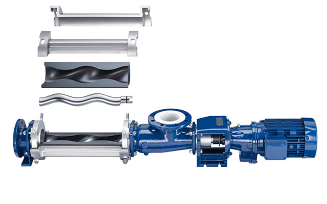
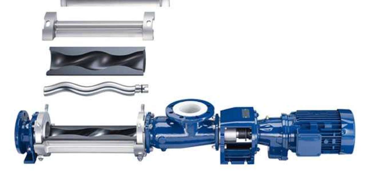
In order to perform maintenance on the sludge screw pump, the pump needs to be disassembled in stages, and a list of those stages is provided for your convenience below:
1. The connection between the motor and the sludge screw pump is severed, and the medium is drained (in order to guarantee that neither the motor nor the toxic medium can cause any harm to anyone); 2. The connection between the motor and the sludge screw pump is severed; 3.2. the link between the motor and the sludge screw pump that was previously present has been severed; 3.2. Take apart the sludge screw pump's discharge body, as well as the rotor and the intermediate shaft.5. Break the rotor and the intermediate shaft down into their component parts individually.5. Take apart the main body of the sludge screw pump that is currently being utilized in the process.5. Take the drive shaft and the seal off of the shaft and remove them from the vehicle.5. Take apart the rotor as well as the intermediate shaft by taking them apart separately.

6. This procedure can be used in a wide variety of contexts, including the surface of the shaft, the interior cavity of the packing shell, and a number of other locations to name a few of them.
When putting together a sludge screw pump, it is absolutely essential that each and every one of the safety precautions that are outlined in the following paragraphs be adhered to in an absolutely stringent manner:
1. Prior to the assembly of the screw pump, each component should be meticulously cleaned and inspected; any components that are discovered to be damaged should be replaced;
The shaft will be able to rotate freely and will not become stuck as long as the bearings are in place after they have been installed stainless steel food grade pumps correctly. This is provided that the bearings have been installed correctly. This is due to the fact that the bearings will prevent the shaft from becoming obstructed.
4. The nuts should be tightened in exactly the same manner regardless of the amount of force that is being applied to the discharge body;
6. The mechanical seal must be installed with care, and after it has been cleaned, the end face of the friction pair must be greased before it can be used. This process must be repeated before the seal can be used. Before we can put it to use, we need to fulfill this prerequisite first. Lubricating oil should be applied to the surface of the inner cavity of the stator as well as the rotor before installing the stator. This should be done before installing the stator. As a direct consequence of this action, the rotor will rotate in a smooth manner as a result. Before moving on to the next step, which involves installing the stator, it is essential to bring this procedure to a successful conclusion.
When you are installing everything and putting it all together, you will need thirty feet in addition to 8.2 millimeters.


