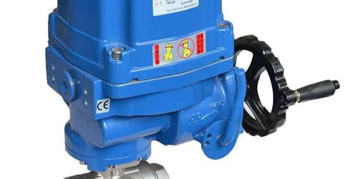
Electric Ball Control Valve Installation Guide
Electric ball control valves are essential components in industrial, commercial, and residential fluid control systems. Proper installation ensures optimal performance, longevity, and safety. This guide provides a detailed, step-by-step approach to installing an electric ball control valve, covering pre-installation checks, wiring procedures, and final testing.
Whether you're a technician, engineer, or DIY enthusiast, following these guidelines will help avoid common errors and ensure smooth valve operation.
Pre-Installation Guidelines
Before starting installation, follow these critical steps to ensure safety and effectiveness:
1. Review Safety Instructions
Read the manufacturer’s safety manual thoroughly.
Ensure all personnel involved understand electrical and mechanical safety procedures.
2. Verify Valve Specifications
Check the actuator label and documentation for:
Pressure rating (maximum allowable pressure)
Temperature range (minimum and maximum)
Media compatibility (ensure the valve material is suitable for the controlled fluid)
3. Select an Appropriate Installation Location
Choose a dry, sheltered, and easily accessible location.
Avoid exposure to moisture, vibration, or mechanical stress.
4. Depressurize and Cool the System
Shut off the fluid supply and release residual pressure.
Allow the system to cool if high-temperature fluids are involved.
5. Inspect and Clean Piping
Check for dirt, debris, or corrosion.
Use appropriate cleaning methods like flushing, brushing, or compressed air.
6. Install an Upstream Filter (If Needed)
Prevent clogging or seat damage if the fluid contains particulates.
Schedule regular filter maintenance.
7. Gather Required Tools and Fittings
Tools:
Adjustable wrench or wrench set
Pipe thread sealant
Welding equipment (for welded connections)
Wire strippers and screwdrivers
Fittings (as required):
Threaded, flanged, or welded adapters
Wiring the Electric Actuator
Proper wiring is crucial for actuator functionality. Incorrect wiring can lead to malfunction or electrical hazards.
1. Identify the Wiring Diagram
Locate the wiring diagram (usually in the manual or on the actuator).
Confirm it matches the actuator type and voltage (AC/DC, 2-wire or 3-wire).
Example: JP Fluid Control Valve Wiring
| Terminal | Connection |
|---|---|
| L | AC Live (120V/240V) |
| N | AC Neutral |
| G | Earth Ground |
| COM | Control Common |
| NO | Normally Open |
| NC | Normally Closed |
2. Prepare the Wires
Strip about 6–8 mm of insulation.
Use ferrules or crimp connectors for secure industrial-grade connections.
3. Connect Power Wires
For AC Actuators:
L → Hot wire
N → Neutral
G → Ground
For DC Actuators:
Connect + and - terminals as indicated.
4. Connect Control Signal Wires
Manual Operation:
NO → COM through a switch
Automated (PLC/DCS):
Connect signal (e.g., 4–20mA, 0–10V) to designated terminals.
Ensure correct polarity.
5. Secure All Connections
Tighten terminal screws properly.
Use cable glands to prevent cable strain or water ingress.
6. Test the Actuator
Power on the system and apply a control signal.
Observe valve movement:
Clockwise = Closing
Counter-clockwise = Opening
If no movement:
Check power supply
Verify control wiring
Inspect for mechanical obstructions
7. Final Inspection
Confirm no exposed or damaged wires.
Ensure actuator housing is sealed (IP65/IP67).
Check for overheating on initial operation.
Installation Best Practices
To enhance durability and reliability:
1. Ensure Proper Alignment
Avoid forcing misaligned pipes.
Use flexible couplings for systems with movement or vibration.
2. Avoid Over-Tightening
Over-tightening can damage threads or flanges.
Follow torque recommendations from the manufacturer.
3. Schedule Periodic Maintenance
Lubricate moving parts (if specified).
Inspect electrical connections annually.
Test valve operation regularly to detect early wear.
Troubleshooting Common Issues
| Issue | Possible Cause | Solution |
|---|---|---|
| Valve not moving | No power | Check circuit breaker and wiring |
| Partial movement | Low voltage | Confirm correct power input |
| Leakage | Loose fittings | Re-tighten or replace seals |
| Erratic motion | Dirty valve seat | Clean or replace ball/seat |
Conclusion
Installing an electric ball control valve involves careful planning, accurate wiring, and thorough testing. Following this guide will help ensure safe, efficient, and long-lasting valve performance.
If further assistance is needed, refer to the manufacturer’s manual or consult a qualified technician.
✅ Proper installation today prevents costly repairs tomorrow.Know more about Google SEO Directory


